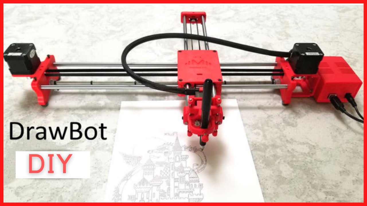
How To Make DIY Pen Plotter / Homework Writing Machine at Home
This Drawing Robot/Pen Plotter/Drawing Machine is similar to the commercially available AxiDraw. It is powered by an Arduino Uno controller, uses a CNC Shield, and GRBL firmware.
The cost to build the Drawing Robot is between $75 and $100 depending on where you buy your parts and whether you already own some of the parts such as the Arduino.
Parts and Materials Required
- 2 x Nema 17 Stepper Motors
- 2 x Linear Rod M8 x 450mm for X Axis
- 2 x Linear Rod M8 x 350mm for Y Axis
- 2 x Linear Rod 3mm for Z Axis (you can get it from old CDROM)
- 1 x Threaded Rod M8 x 480mm
- 8 x LM8UU Bearings
- 1 x Servo Sg90
- 1 x Spring 5m (from ball point pen)
- 2 x GT2 Pulley, 16 teeth
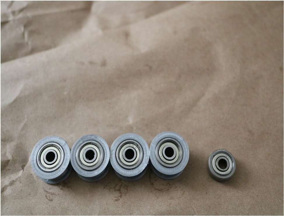
- 5 x Bearing 624zz
- 1 x 2000mm GT2 belt
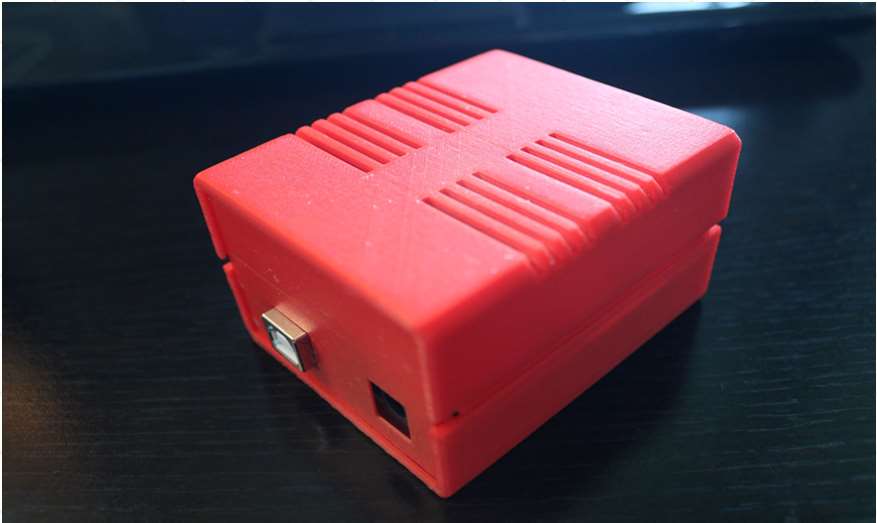
- 1 x Arduino Uno
- 1 x CNC Shield
- 2 x A4988 Stepper driver with heatsink
- 6 x Jumpers
- 1 x 12V 2A Power Supply
Nuts
- 7 x M3-0.5
- 5 x M4-0.7
- 4 x 5/16in-18
Screws
- 13 x Phillips M3-0.5 x 16mm
- 4 x Phillips M3-0.5 x 6mm
- 5 x Phillips M4-0.7x 35mm
- 1 x Hex M3-0.5 x 20mm
Washers
- 4 x 5/16in washer
- 4 x M3 washers
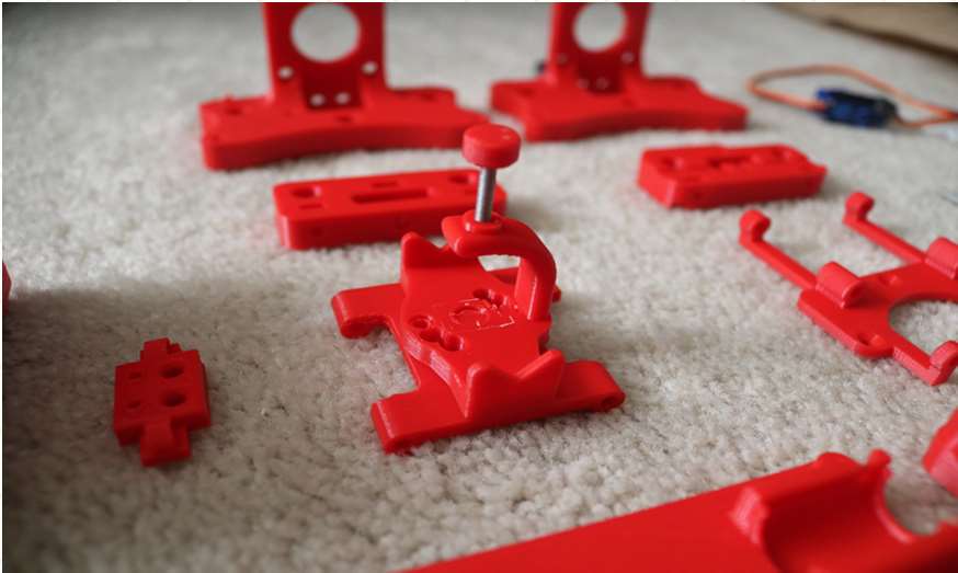
3D Printing
- Download the files from Thingiverse
- Open the 3D models in Cura or any other slicer(Sli3er, Simplify 3D, etc.)
- Use 75% infill on all the parts (An infill of 70 – 100% will work as well)
- Printed all the parts with 0.10 – 0.20 mm layer height
- Printed with Hatchbox Red PLA
- Use supports on the Penholder, Slider, X_Support_L and the X_Support_R
Note: The longest part took around 9hrs and the shortest took 30 minutes to print
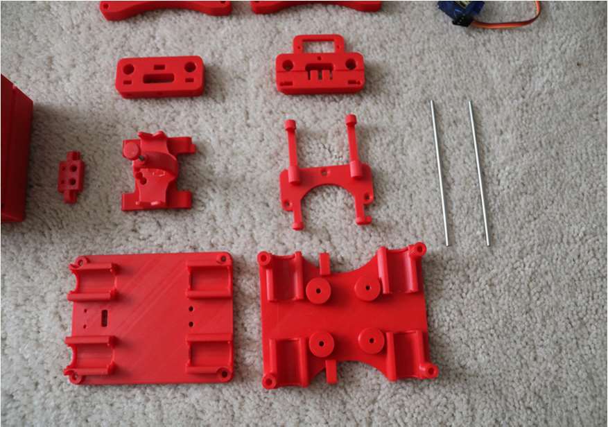
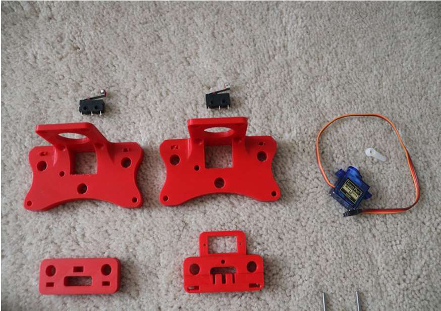
3D Printed Parts
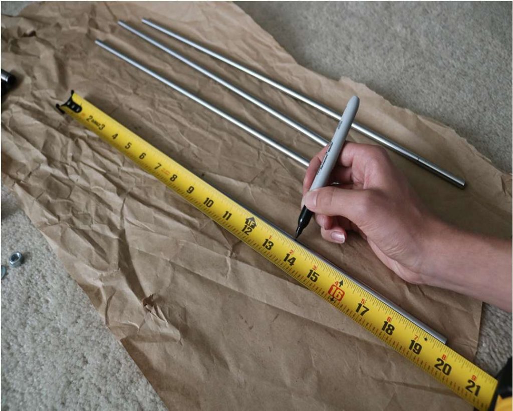
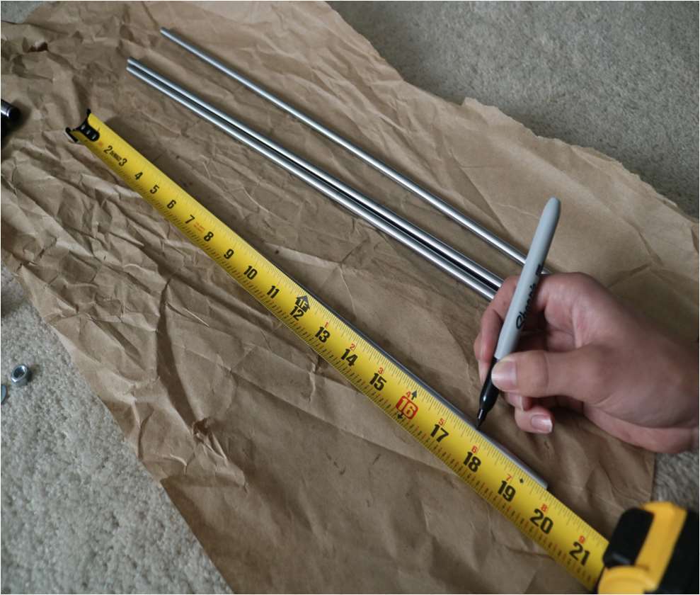
Cut your Linear Rods
Use a measuring tape and sharpie to mark the spots where the rods need to be
cut
- Use a vise to hold the rods in place when you cut them
- Remember that you need (2) 350mm and (2) 450mm long linear rods
- On the threaded rod, mark your cutting point at 470mm
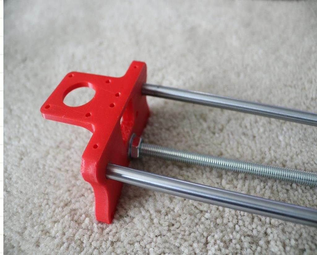
Assemble the X-Axis (Linear/Threaded Rods)
Take the (2) 450mm linear rods and insert them into either x-support part
- Use may need to use a round file to smooth out the holes that you insert them in
- Also, you can use a rubber mallet to help insert the rods
Now take the threaded rod and insert it in the hole below. Feed a 5/16in washer and 5/16in nut on both sides of the x-support part
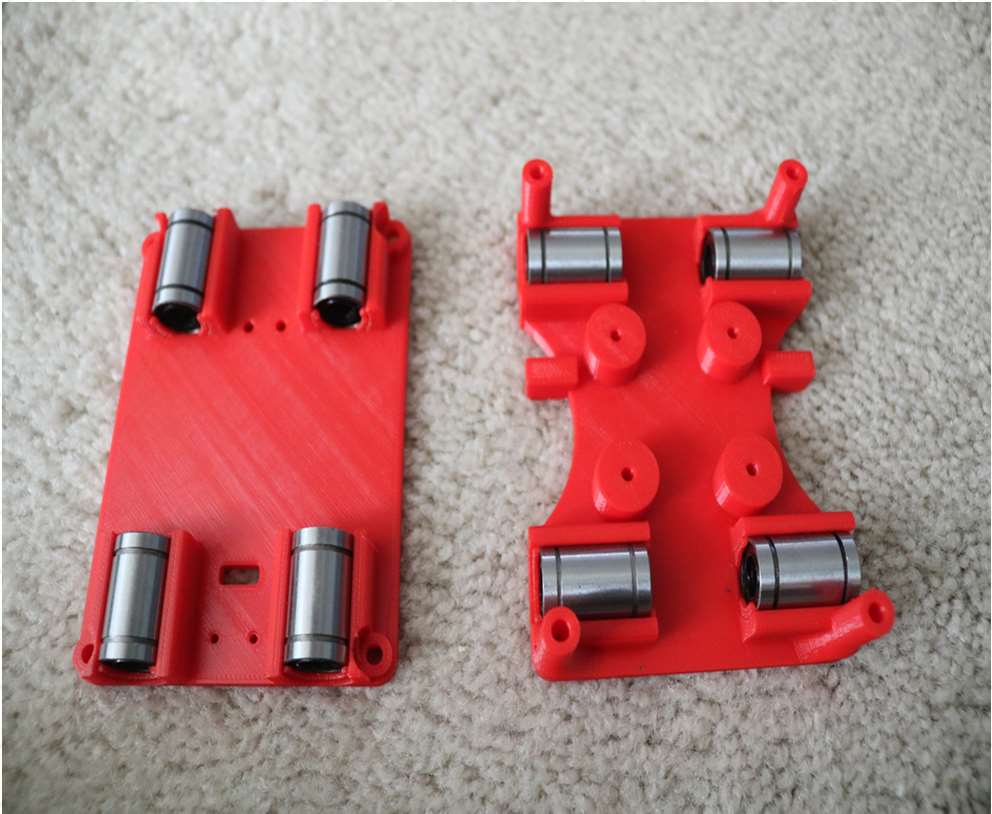
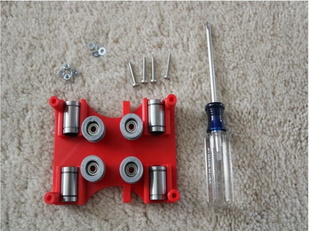
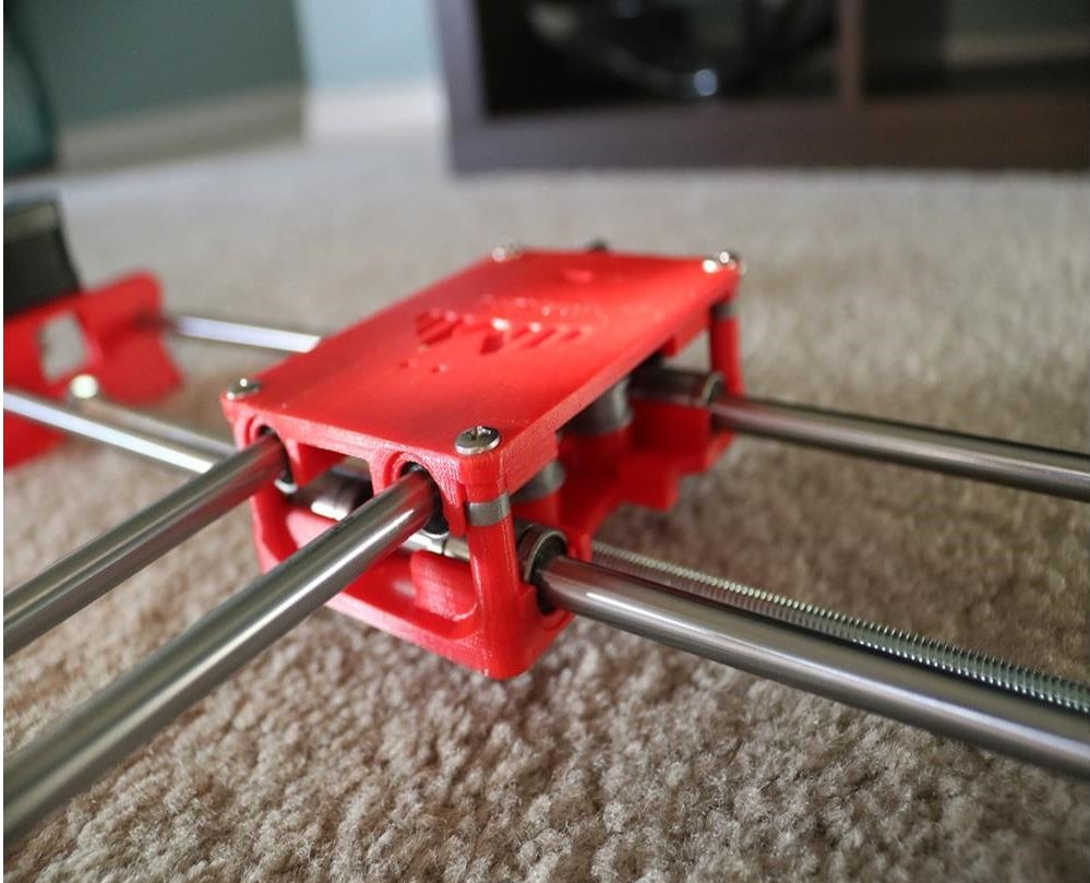
Assemble the X-Axis (Bearings)
Now you want to push the LM8UU bearings into their place on the top and bottom clamshell (The top and bottom clamshell take (4) bearings each)
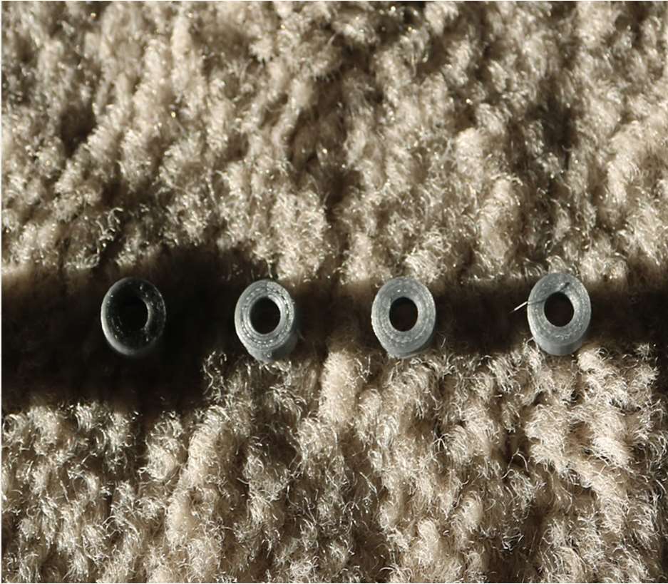
Take (4) 624zz bearings and push them through the 3D-printed idler pulleys. Leave the 5th bearing for later when you assemble the Y-axis
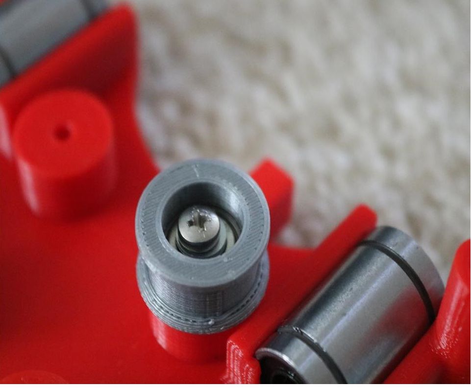
Assemble the X-Axis (Carriage)
- Get (4) M3-0.5 x 20mm screws, (4) M3 nuts, (4) M3 washers and (4) 624zz bearings with the idler pulleys installed
- Take one screw and feed a washer through it, the washer will rest on the bearing. The nut will be at the bottom of the carriage, which will secure the bearing in place
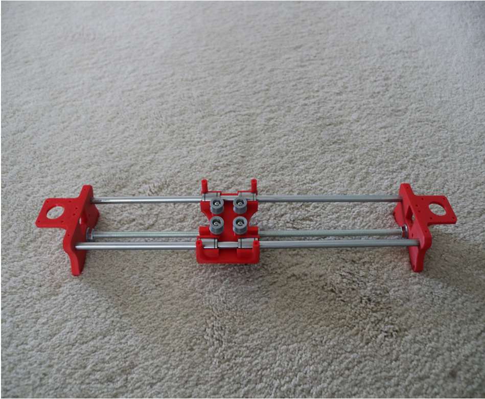
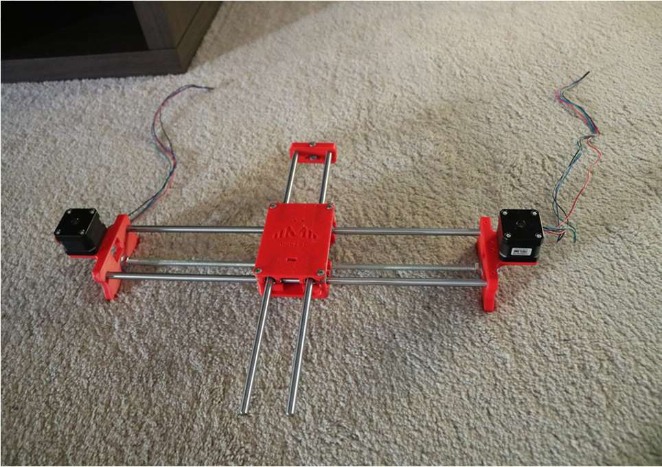
Assemble the X-Axis (X-Support)
- Slide the clamshell through the 450mm (X-axis) linear rods
- Use a rubber mallet again to attach the last X-support on the linear rods
- Make sure that the rods stick out equally on both sides
- Slide the other end of the threaded rod through the hole on the X-support
- Put on the last set of nuts and washers to hold the X-support in place
- Now that the X-axis is complete, you can use (2) Phillips M3-0.5 x 16mm screws per X-support to help keep the linear rods from sliding
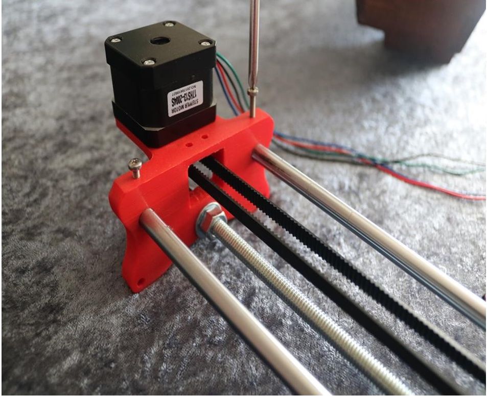
Assemble the X-Axis (Stepper Motors)
- Use an appropriate sized allen wrench to attach the 16 teeth pulleys on the stepper motor shafts
- Flipping the entire chassis around will make it easier to attach the stepper motors
- Use (8) M3-0.5 x 6mm screws and a Phillips screwdriver to attach the (2) stepper motors
Assemble the Y-Axis (Clamshell)
(Optional if you have problems keeping belt on bearings)
- Grab (4) M4-0.5 x 35mm screws and (4) M4 nuts
- Make sure that you have the (4) idler pulleys (Download from Thingiversa) and the (4) washers printed
- Insert the washers in between the two clamshells, with a screw in between
- Screw the top and bottom clamshells together
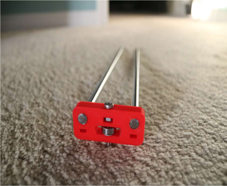
Assemble the Y-Axis (Y- Back/Front)
Y-Back
- Take the (2) 350mm linear rods and insert them the Y-back piece by using a rubber mallet
- Get (1) M4-0.5 x 35 screw, (1) M4 nut and the 5th 624zz bearing
- Get (2) M3-0.5 x 16 screws to secure the linear rods
- Slide in the bearing when inserting the screw through the Y-back piece
Y-Front
- Slide the the linear rods/Y-back piece through the LM8UU bearings and attach the Y-front piece using a rubber mallet
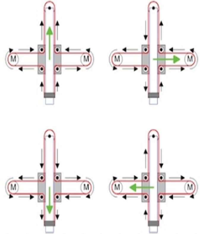
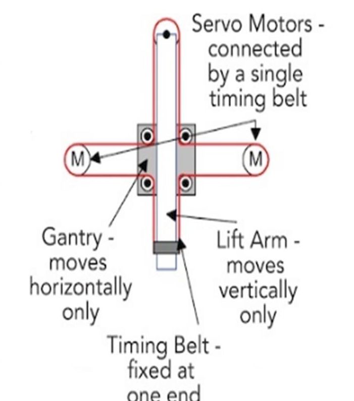
Assemble the X-Y Axis (Belt)
- Use a pair of needle nose pliers to help guide the GT2 belt more easily through the clamshell
- Take the two ends of the belt and slide them through the “teeth” on the Base Slider
- The belt should be tight and not loose
- Note that once the GT2 belt is on, it is normal for the clamshell not to move easily
Belt Diagram
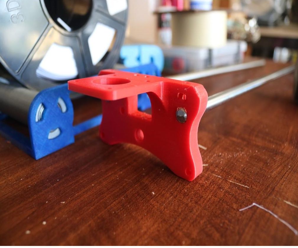
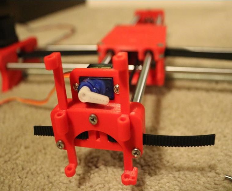
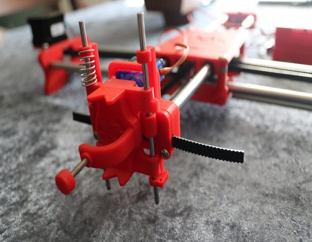
Assemble the Z-Axis
- Get (2) 3mm linear rods and the following 3D printed parts (Slider, Pen Holder, Base Slide, 3MM Metric Thumb Screw)
- Get (1) Hex M3-0.5 x 20mm screw and the Metric Thumb Screw and push them together. Use superglue to keep it together.
- Get (3) M3-0.5 x 16mm screws which you will use the secure the Base Slide to the Y-Front part. You may need to use (3) M3-0.5 nuts in order to hold it in place
- Push the Slider and Pen Holder together to make one piece
- Now take that new part and the (2) 3mm linear rods and slide the rods through the holes. Place a small spring in between the two parts so there is a little bit of pressure to lift the Slider. You may need to cut the spring a bit until there is an adequate amount of pressure on the slider.
Step By Step Video
The Original Instructions by Henry Arnold Jonathan K
i constructed all the machine
but when i press X+ the both X and Y axis are moving what is the problem
double check the steppers wiring
Have you solved it?
I have the same problem with my machine, when I press X+, it’s necessary both motors move at same time, but, only one of them move…
Did you solve this problem?
Same problem how to solve ,?
Is it true that you didn’t use the microswitches in the final design?
Hello how to co figurę this machine to RUN on GRBL. What I mean is that GRBL interprets commands for x axis and y axis independently and if I look on your belt diagram it looks like both Motors have to run at the same time in order to move the carriage along y axis… How did you do that?
Have you solved it?
Thank you, thank you. It’s a very good built.
Is it possible to modify it to draw using brush ang oil based paint ?
Could you please tell what software/plug in and which version do you use to generate g-code for this machine?
inkscape
Hello, what is the width of your belt? 6mm or 10mm?
Thanks!